
Team Members
Joshua Carson, Charles Hanlon, Jack Passero, Alex Patton, Brett F, Chris Hackbardt, Ian Schiess, Tao Dobbins, Giancarlo Gomez, Aaron Klein
Abstract

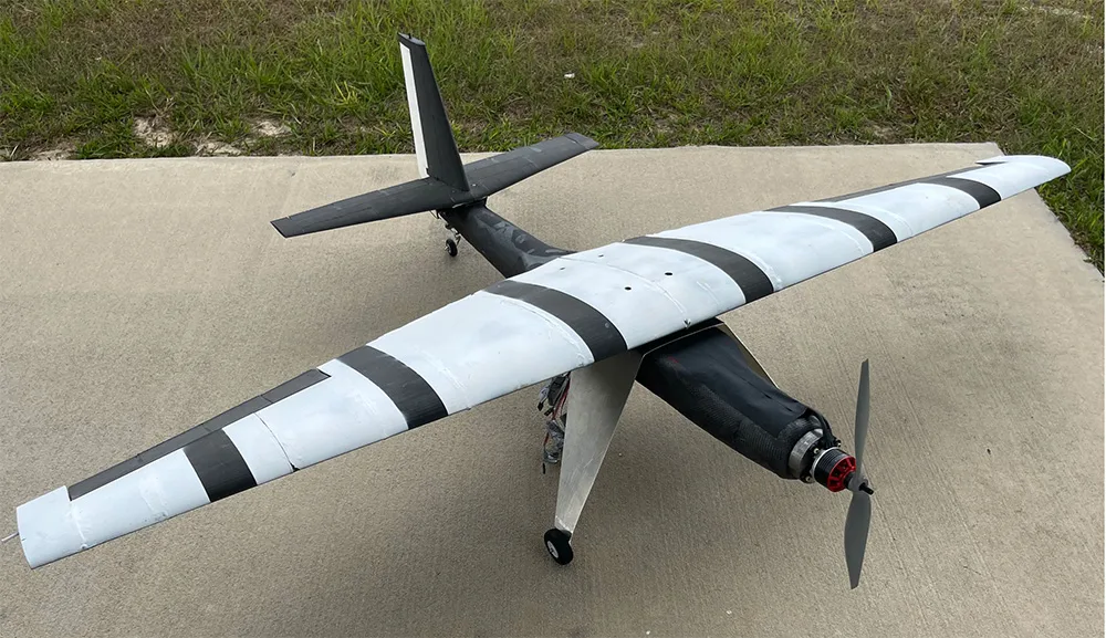
This report first explains the goal of our project and design requirements we put in place to have the best chance of success. The main requirement of the project is to build an airplane then fly three laps around a course by the end of the semester. Major geometries of the aircraft were also set. The wingspan would be five feet, the desired cruise speed would be 40 mph, and the estimated weight would be 6 pounds. Next more detailed design choices were made. Due to stall characteristics an SD7062 airfoil was selected for the wing. A taper ratio of 0.4 was selected, an aspect ratio of 6.68 was calculated, and an incidence angle of three degrees was selected to minimize drag. A fuselage design with a circular cross section and a length of 45 inches made from lightweight PLA was then explained. 32 different propulsion systems were analyzed, with the best scoring system being a Badass 3515-580 motor with a 13×5.5E propellor. The landing gear configuration was selected to be a taildragger to allow for more pilot control while on the ground. Carbon fiber spars were then selected, designed to be inside of the main wing, and giving the wing structure a factor of safety of 3.17 at a maximum stress flight condition. Finite element analysis was used to confirm these results. Tail design and stability analysis were then completed. Using a static stability analysis, the vertical tail and horizontal tail size was designed to be 0.32 ft2 and 0.86 ft2, respectively. This tail design resulted in a statically stable airplane and dynamic stability values which were acceptable. To manufacture the aircraft, 3D printing was mostly used, but some sheet metal fabrication was used for the landing gear, and a carbon fiber layup was done as a final experimental aircraft. Most components could be assembled using epoxy or CA glue, but some needed to be bolted on, such as the landing gear. Flight tests were then explained. The first and second flights resulted in repairable crashes, and the third flight resulted in a successful mission completing well over the required three laps. The aircraft with a carbon fiber fuselage was tested later resulting in two crashes.
Pitch Video
3D Interactive Product Model
The following is an interactive 3D model of the product design. You can view and rotate the product assembly in different orientations and views, including an exploded view to see the various parts that make up the assembly.